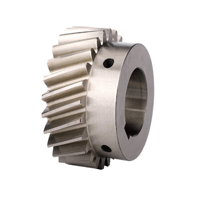
Issue: New Guarantee: Unavailable Shape: Rack Gear Relevant Industries: Building Content Outlets, Manufacturing Plant, Retail, Building functions Excess weight (KG): 2.six Showroom Place: None Online video outgoing-inspection: Offered Machinery Check Report: Provided Marketing Type: Ordinary Item Warranty of core parts: Not Offered Core Elements: Motor, Gear Product Amount: LX571-10 Material: Stainless steel, stainless metal Processing: Hobbing Normal or Nonstandard: Common Identify: helical gear rack Color: silver Support: ODM OEM Srvice Utilization: Slidng gate High quality: Substantial-good quality Dimensions: M2 24*24*one thousand/2000mm Packaging Details: Merchandise Title: helical gear rack for sliding doorPackage: 4pcs/box 500pcs/pallet Port: ZheJiang /HangZhou
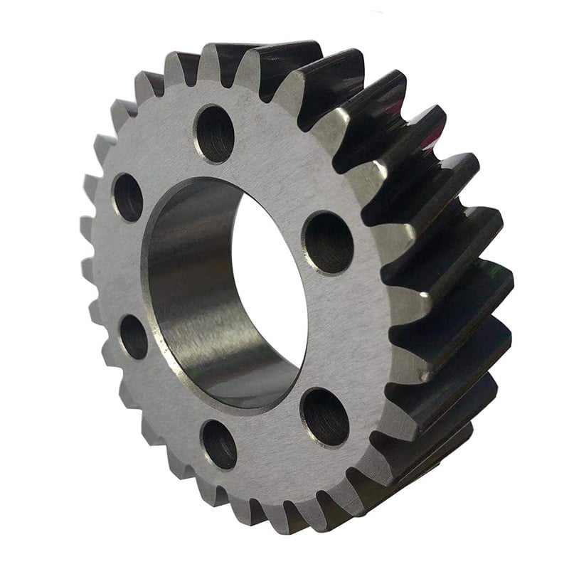
helical gear rack We’ C45 metal customized straight enamel module 1. 1 1.5 2. 2 2.5 3 4 5 6 pinion equipment M1. M1 M1.5 M2 M2.5 M3 M4 M5 M6 with keyway d like to welcome you to our manufacturing facility. XIHU (WEST LAKE) DIS.N was started in 1998 in HangZhou City of ZHangZhoug Province,China.We focus in design and manufacture of beauty deals. Our primary productions are Gear Rack,Pinion,Sliding Gate Monitor andother add-ons for automatic sliding doorway.We are happy to introduce our factory and passionate workers. I hope we can construct a extended-lasting relationship. Q: Are you trading company or company ?A: We are manufacturing unit.Q: How extended is your shipping time?A: Usually it is 3-7 days if the products are in inventory. or it is 15-20 times if the goods are not instock, it is in accordance to quantity.Q: Do you offer samples ? is it cost-free or extra ?A: Of course, we could supply the sample for cost-free cost but do not pay out the price of freight.Q: What is your conditions of payment ?A: Payment=1000USD, thirty% T/T in progress ,balancebefore shippment.If you have one more concern, pls come to feel free to get in touch with us as underneath.
Benefits and Uses of Miter Gears
If you’ve ever looked into the differences between miter gears, you’re probably wondering how to choose between a Straight toothed and Hypoid one. Before you decide, however, make sure you know about backlash and what it means. Backlash is the difference between the addendum and dedendum, and it prevents jamming of the gears, protects the mating gear surfaces, and allows for thermal expansion during operation.
Spiral bevel gears
Spiral bevel gears are designed to increase efficiency and reduce cost. The spiral shape creates a profile in which the teeth are cut with a slight curve along their length, making them an excellent choice for heavy-duty applications. Spiral bevel gears are also hypoid gears, with no offsets. Their smaller size means that they are more compact than other types of right-angle gears, and they are much quieter than other types of gear. Spiral bevel gears feature helical teeth arranged in a 90-degree angle. The design features a slight curve to the teeth, which reduces backlash while increasing flexibility. Because they have no offsets, they won’t slip during operation. Spiral bevel gears also have less backlash, making them an excellent choice for high-speed applications. They are also carefully spaced to distribute lubricant over a larger area. They are also very accurate and have a locknut design that prevents them from moving out of alignment. In addition to the geometric design of bevel gears, CZPT can produce 3D models of spiral bevel gears. This software has gained widespread attention from many companies around the world. In fact, CZPT, a major manufacturer of 5-axis milling machines, recently machined a prototype using a spiral bevel gear model. These results prove that spiral bevel gears can be used in a variety of applications, ranging from precision machining to industrial automation. Spiral bevel gears are also commonly known as hypoid gears. Hypoid gears differ from spiral bevel gears in that their pitch surface is not at the center of the meshing gear. The benefit of this gear design is that it can handle large loads while maintaining its unique features. They also produce less heat than their bevel counterparts, which can affect the efficiency of nearby components.
Straight toothed miter gears
Miter gears are bevel gears that have a pitch angle of 90 degrees. Their gear ratio is 1:1. Miter gears come in straight and spiral tooth varieties and are available in both commercial and high precision grades. They are a versatile tool for any mechanical application. Below are some benefits and uses of miter gears. A simple explanation of the basic principle of this gear type is given. Read on for more details. When selecting a miter gear, it is important to choose the right material. Hard faced, high carbon steel is appropriate for applications requiring high load, while nylon and injection molding resins are suitable for lower loads. If a particular gear becomes damaged, it’s advisable to replace the entire set, as they are closely linked in shape. The same goes for spiral-cut miter gears. These geared products should be replaced together for proper operation. Straight bevel gears are the easiest to manufacture. The earliest method was using an indexing head on a planer. Modern manufacturing methods, such as the Revacycle and Coniflex systems, made the process more efficient. CZPT utilizes these newer manufacturing methods and patented them. However, the traditional straight bevel is still the most common and widely used type. It is the simplest to manufacture and is the cheapest type. SDP/Si is a popular supplier of high-precision gears. The company produces custom miter gears, as well as standard bevel gears. They also offer black oxide and ground bore and tooth surfaces. These gears can be used for many industrial and mechanical applications. They are available in moderate quantities from stock and in partial sizes upon request. There are also different sizes available for specialized applications.
Hypoid bevel gears
The advantages of using Hypoid bevel and helical gears are obvious. Their high speed, low noise, and long life make them ideal for use in motor vehicles. This type of gear is also becoming increasingly popular in the power transmission and motion control industries. Compared to standard bevel and helical gears, they have a higher capacity for torque and can handle high loads with less noise. Geometrical dimensioning of bevel/hypoid bevel gears is essential to meet ANSI/AGMA/ISO standards. This article examines a few ways to dimension hypoid bevel and helical gears. First, it discusses the limitations of the common datum surface when dimensioning bevel/helical gear pairs. A straight line can’t be parallel to the flanks of both the gear and the pinion, which is necessary to determine “normal backlash.” Second, hypoid and helical gears have the same angular pitch, which makes the manufacturing process easier. Hypoid bevel gears are usually made of two gears with equal angular pitches. Then, they are assembled to match one another. This reduces noise and vibration, and increases power density. It is recommended to follow the standard and avoid using gears that have mismatched angular pitches. Third, hypoid and helical gears differ in the shape of the teeth. They are different from standard gears because the teeth are more elongated. They are similar in appearance to spiral bevel gears and worm gears, but differ in geometry. While helical gears are symmetrical, hypoid bevel gears are non-conical. As a result, they can produce higher gear ratios and torque.
Crown bevel gears
The geometrical design of bevel gears is extremely complex. The relative contact position and flank form deviations affect both the paired gear geometry and the tooth bearing. In addition, paired gears are also subject to process-linked deviations that affect the tooth bearing and backlash. These characteristics require the use of narrow tolerance fields to avoid quality issues and production costs. The relative position of a miter gear depends on the operating parameters, such as the load and speed. When selecting a crown bevel gear for a miter-gear system, it is important to choose one with the right tooth shape. The teeth of a crown-bevel gear can differ greatly in shape. The radial pitch and diametral pitch cone angles are the most common. The tooth cone angle, or “zerol” angle, is the other important parameter. Crown bevel gears have a wide range of tooth pitches, from flat to spiral. Crown bevel gears for miter gear are made of high-quality materials. In addition to metal, they can be made of plastic or pre-hardened alloys. The latter are preferred as the material is less expensive and more flexible than steel. Furthermore, crown bevel gears for miter gears are extremely durable, and can withstand extreme conditions. They are often used to replace existing gears that are damaged or worn. When selecting a crown bevel gear for a miter gear, it is important to know how they relate to each other. This is because the crown bevel gears have a 1:1 speed ratio with a pinion. The same is true for miter gears. When comparing crown bevel gears for miter gears, be sure to understand the radii of the pinion and the ring on the pinion.
Shaft angle requirements for miter gears
Miter gears are used to transmit motion between intersecting shafts at a right angle. Their tooth profile is shaped like the mitre hat worn by a Catholic bishop. Their pitch and number of teeth are also identical. Shaft angle requirements vary depending on the type of application. If the application is for power transmission, miter gears are often used in a differential arrangement. If you’re installing miter gears for power transmission, you should know the mounting angle requirements. Shaft angle requirements for miter gears vary by design. The most common arrangement is perpendicular, but the axes can be angled to almost any angle. Miter gears are also known for their high precision and high strength. Their helix angles are less than ten degrees. Because the shaft angle requirements for miter gears vary, you should know which type of shaft angle you require before ordering. To determine the right pitch cone angle, first determine the shaft of the gear you’re designing. This angle is called the pitch cone angle. The angle should be at least 90 degrees for the gear and the pinion. The shaft bearings must also be capable of bearing significant forces. Miter gears must be supported by bearings that can withstand significant forces. Shaft angle requirements for miter gears vary from application to application. For industrial use, miter gears are usually made of plain carbon steel or alloy steel. Some materials are more durable than others and can withstand higher speeds. For commercial use, noise limitations may be important. The gears may be exposed to harsh environments or heavy machine loads. Some types of gears function with teeth missing. But be sure to know the shaft angle requirements for miter gears before you order one.
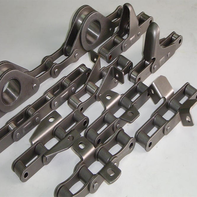
Issue: New Guarantee: 6 Months Condition: Worm Applicable Industries: Accommodations, Garment Outlets, Constructing Substance Shops, Manufacturing Plant, Equipment Restore Retailers, Meals & Beverage Manufacturing facility, Farms, Cafe, Home Use, Retail, Foods Shop, Printing Shops, Construction works , Vitality & Mining, Meals & Beverage Retailers, Promoting Organization Fat (KG): .one After Guarantee Services: Video clip technological support Neighborhood Service Location: None Showroom Spot: None Online video outgoing-inspection: Provided Machinery Take a look at Report: Provided Advertising and marketing Type: Normal Solution Warranty of core elements: 1 Year Main Elements: Engine, Bearing, Gearbox, Motor, Pressure vessel, Gear, Pump Materials: Metal, Stainless metal, Metal, Brass, C45 Metal, Copper, Aluminium, Alloy,and so on Standard or Nonstandard: Nonstandard Course: Customized Area Remedy: OEM Produced Tolerance: +/-. for ZF 7075-T and many others.
2) Stainless steel: 303, 304, 316L, 17-4(SUS630) and so forth.
3) Metal: 4140, Q235, Q345B, twenty#, 45# etc.
4) Titanium: TA1, TA2/GR2, TA4/GR5, TC4, TC18 and so forth.
5) Brass: C36 Journey Reduction Gearbox For CZPT China.Q7: Will my drawings be safe right after sending to you?A7: Of course, we will maintain them well and not launch to third party without your permission.
Benefits and Uses of Miter Gears
If you’ve ever looked into the differences between miter gears, you’re probably wondering how to choose between a Straight toothed and Hypoid one. Before you decide, however, make sure you know about backlash and what it means. Backlash is the difference between the addendum and dedendum, and it prevents jamming of the gears, protects the mating gear surfaces, and allows for thermal expansion during operation.
Spiral bevel gears
Spiral bevel gears are designed to increase efficiency and reduce cost. The spiral shape creates a profile in which the teeth are cut with a slight curve along their length, making them an excellent choice for heavy-duty applications. Spiral bevel gears are also hypoid gears, with no offsets. Their smaller size means that they are more compact than other types of right-angle gears, and they are much quieter than other types of gear. Spiral bevel gears feature helical teeth arranged in a 90-degree angle. The design features a slight curve to the teeth, which reduces backlash while increasing flexibility. Because they have no offsets, they won’t slip during operation. Spiral bevel gears also have less backlash, making them an excellent choice for high-speed applications. They are also carefully spaced to distribute lubricant over a larger area. They are also very accurate and have a locknut design that prevents them from moving out of alignment. In addition to the geometric design of bevel gears, CZPT can produce 3D models of spiral bevel gears. This software has gained widespread attention from many companies around the world. In fact, CZPT, a major manufacturer of 5-axis milling machines, recently machined a prototype using a spiral bevel gear model. These results prove that spiral bevel gears can be used in a variety of applications, ranging from precision machining to industrial automation. Spiral bevel gears are also commonly known as hypoid gears. Hypoid gears differ from spiral bevel gears in that their pitch surface is not at the center of the meshing gear. The benefit of this gear design is that it can handle large loads while maintaining its unique features. They also produce less heat than their bevel counterparts, which can affect the efficiency of nearby components.
Straight toothed miter gears
Miter gears are bevel gears that have a pitch angle of 90 degrees. Their gear ratio is 1:1. Miter gears come in straight and spiral tooth varieties and are available in both commercial and high precision grades. They are a versatile tool for any mechanical application. Below are some benefits and uses of miter gears. A simple explanation of the basic principle of this gear type is given. Read on for more details. When selecting a miter gear, it is important to choose the right material. Hard faced, high carbon steel is appropriate for applications requiring high load, while nylon and injection molding resins are suitable for lower loads. If a particular gear becomes damaged, it’s advisable to replace the entire set, as they are closely linked in shape. The same goes for spiral-cut miter gears. These geared products should be replaced together for proper operation. Straight bevel gears are the easiest to manufacture. The earliest method was using an indexing head on a planer. Modern manufacturing methods, such as the Revacycle and Coniflex systems, made the process more efficient. CZPT utilizes these newer manufacturing methods and patented them. However, the traditional straight bevel is still the most common and widely used type. It is the simplest to manufacture and is the cheapest type. SDP/Si is a popular supplier of high-precision gears. The company produces custom miter gears, as well as standard bevel gears. They also offer black oxide and ground bore and tooth surfaces. These gears can be used for many industrial and mechanical applications. They are available in moderate quantities from stock and in partial sizes upon request. There are also different sizes available for specialized applications.
Hypoid bevel gears
The advantages of using Hypoid bevel and helical gears are obvious. Their high speed, low noise, and long life make them ideal for use in motor vehicles. This type of gear is also becoming increasingly popular in the power transmission and motion control industries. Compared to standard bevel and helical gears, they have a higher capacity for torque and can handle high loads with less noise. Geometrical dimensioning of bevel/hypoid bevel gears is essential to meet ANSI/AGMA/ISO standards. This article examines a few ways to dimension hypoid bevel and helical gears. First, it discusses the limitations of the common datum surface when dimensioning bevel/helical gear pairs. A straight line can’t be parallel to the flanks of both the gear and the pinion, which is necessary to determine “normal backlash.” Second, hypoid and helical gears have the same angular pitch, which makes the manufacturing process easier. Hypoid bevel gears are usually made of two gears with equal angular pitches. Then, they are assembled to match one another. This reduces noise and vibration, and increases power density. It is recommended to follow the standard and avoid using gears that have mismatched angular pitches. Third, hypoid and helical gears differ in the shape of the teeth. They are different from standard gears because the teeth are more elongated. They are similar in appearance to spiral bevel gears and worm gears, but differ in geometry. While helical gears are symmetrical, hypoid bevel gears are non-conical. As a result, they can produce higher gear ratios and torque.
Crown bevel gears
The geometrical design of bevel gears is extremely complex. The relative contact position and flank form deviations affect both the paired gear geometry and the tooth bearing. In addition, paired gears are also subject to process-linked deviations that affect the tooth bearing and backlash. These characteristics require the use of narrow tolerance fields to avoid quality issues and production costs. The relative position of a miter gear depends on the operating parameters, such as the load and speed. When selecting a crown bevel gear for a miter-gear system, it is important to choose one with the right tooth shape. The teeth of a crown-bevel gear can differ greatly in shape. The radial pitch and diametral pitch cone angles are the most common. The tooth cone angle, or “zerol” angle, is the other important parameter. Crown bevel gears have a wide range of tooth pitches, from flat to spiral. Crown bevel gears for miter gear are made of high-quality materials. In addition to metal, they can be made of plastic or pre-hardened alloys. The latter are preferred as the material is less expensive and more flexible than steel. Furthermore, crown bevel gears for miter gears are extremely durable, and can withstand extreme conditions. They are often used to replace existing gears that are damaged or worn. When selecting a crown bevel gear for a miter gear, it is important to know how they relate to each other. This is because the crown bevel gears have a 1:1 speed ratio with a pinion. The same is true for miter gears. When comparing crown bevel gears for miter gears, be sure to understand the radii of the pinion and the ring on the pinion.
Shaft angle requirements for miter gears
Miter gears are used to transmit motion between intersecting shafts at a right angle. Their tooth profile is shaped like the mitre hat worn by a Catholic bishop. Their pitch and number of teeth are also identical. Shaft angle requirements vary depending on the type of application. If the application is for power transmission, miter gears are often used in a differential arrangement. If you’re installing miter gears for power transmission, you should know the mounting angle requirements. Shaft angle requirements for miter gears vary by design. The most common arrangement is perpendicular, but the axes can be angled to almost any angle. Miter gears are also known for their high precision and high strength. Their helix angles are less than ten degrees. Because the shaft angle requirements for miter gears vary, you should know which type of shaft angle you require before ordering. To determine the right pitch cone angle, first determine the shaft of the gear you’re designing. This angle is called the pitch cone angle. The angle should be at least 90 degrees for the gear and the pinion. The shaft bearings must also be capable of bearing significant forces. Miter gears must be supported by bearings that can withstand significant forces. Shaft angle requirements for miter gears vary from application to application. For industrial use, miter gears are usually made of plain carbon steel or alloy steel. Some materials are more durable than others and can withstand higher speeds. For commercial use, noise limitations may be important. The gears may be exposed to harsh environments or heavy machine loads. Some types of gears function with teeth missing. But be sure to know the shaft angle requirements for miter gears before you order one.
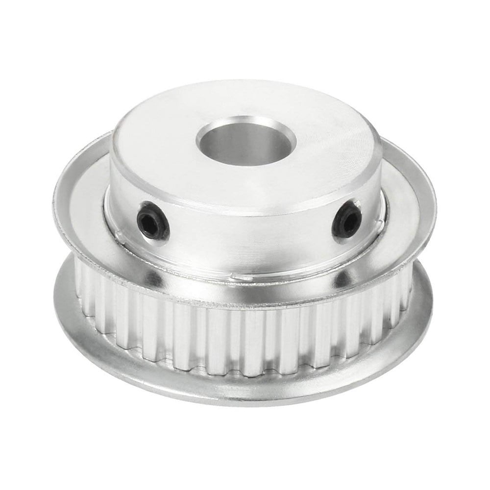
HangZhou CZPT Precision Equipment Co., Ltd. proven in 2009, it is a specialist provider of hydraulic chrome plated piston rods ,inducton linear shaft, linear motion bearing ,linear guide, linear module and ball screw etc. Our organization positioned in HangZhou, which is a foreign trade oriented economic produced metropolis, adjacent to intercontinental port city ZheJiang .
Before you start designing your own spur gear, you need to understand its main components. Among them are Forging, Keyway, Spline, Set screw and other types. Understanding the differences between these types of spur gears is essential for making an informed decision. To learn more, keep reading. Also, don’t hesitate to contact me for assistance! Listed below are some helpful tips and tricks to design a spur gear. Hopefully, they will help you design the spur gear of your dreams.
Forging spur gears
Forging spur gears is one of the most important processes of automotive transmission components. The manufacturing process is complex and involves several steps, such as blank spheroidizing, hot forging, annealing, phosphating, and saponification. The material used for spur gears is typically 20CrMnTi. The process is completed by applying a continuous through extrusion forming method with dies designed for the sizing band length L and Splitting angle thickness T. The process of forging spur gears can also use polyacetal (POM), a strong plastic commonly used for the manufacture of gears. This material is easy to mold and shape, and after hardening, it is extremely stiff and abrasion resistant. A number of metals and alloys are used for spur gears, including forged steel, stainless steel, and aluminum. Listed below are the different types of materials used in gear manufacturing and their advantages and disadvantages. A spur gear’s tooth size is measured in modules, or m. Each number represents the number of teeth in the gear. As the number of teeth increases, so does its size. In general, the higher the number of teeth, the larger the module is. A high module gear has a large pressure angle. It’s also important to remember that spur gears must have the same module as the gears they are used to drive.
Set screw spur gears
A modern industry cannot function without set screw spur gears. These gears are highly efficient and are widely used in a variety of applications. Their design involves the calculation of speed and torque, which are both critical factors. The MEP model, for instance, considers the changing rigidity of a tooth pair along its path. The results are used to determine the type of spur gear required. Listed below are some tips for choosing a spur gear: Type A. This type of gear does not have a hub. The gear itself is flat with a small hole in the middle. Set screw gears are most commonly used for lightweight applications without loads. The metal thickness can range from 0.25 mm to 3 mm. Set screw gears are also used for large machines that need to be strong and durable. This article provides an introduction to the different types of spur gears and how they differ from one another. Pin Hub. Pin hub spur gears use a set screw to secure the pin. These gears are often connected to a shaft by dowel, spring, or roll pins. The pin is drilled to the precise diameter to fit inside the gear, so that it does not come loose. Pin hub spur gears have high tolerances, as the hole is not large enough to completely grip the shaft. This type of gear is generally the most expensive of the three.
Keyway spur gears
In today’s modern industry, spur gear transmissions are widely used to transfer power. These types of transmissions provide excellent efficiency but can be susceptible to power losses. These losses must be estimated during the design process. A key component of this analysis is the calculation of the contact area (2b) of the gear pair. However, this value is not necessarily applicable to every spur gear. Here are some examples of how to calculate this area. (See Figure 2) Spur gears are characterized by having teeth parallel to the shafts and axis, and a pitch line velocity of up to 25 m/s is considered high. In addition, they are more efficient than helical gears of the same size. Unlike helical gears, spur gears are generally considered positive gears. They are often used for applications in which noise control is not an issue. The symmetry of the spur gear makes them especially suitable for applications where a constant speed is required. Besides using a helical spur gear for the transmission, the gear can also have a standard tooth shape. Unlike helical gears, spur gears with an involute tooth form have thick roots, which prevents wear from the teeth. These gears are easily made with conventional production tools. The involute shape is an ideal choice for small-scale production and is one of the most popular types of spur gears.
Spline spur gears
When considering the types of spur gears that are used, it’s important to note the differences between the two. A spur gear, also called an involute gear, generates torque and regulates speed. It’s most common in car engines, but is also used in everyday appliances. However, one of the most significant drawbacks of spur gears is their noise. Because spur gears mesh only one tooth at a time, they create a high amount of stress and noise, making them unsuitable for everyday use. The contact stress distribution chart represents the flank area of each gear tooth and the distance in both the axial and profile direction. A high contact area is located toward the center of the gear, which is caused by the micro-geometry of the gear. A positive l value indicates that there is no misalignment of the spline teeth on the interface with the helix hand. The opposite is true for negative l values. Using an upper bound technique, Abdul and Dean studied the forging of spur gear forms. They assumed that the tooth profile would be a straight line. They also examined the non-dimensional forging pressure of a spline. Spline spur gears are commonly used in motors, gearboxes, and drills. The strength of spur gears and splines is primarily dependent on their radii and tooth diameter. SUS303 and SUS304 stainless steel spur gears
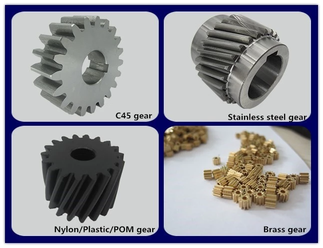
Stainless steel spur gears are manufactured using different techniques, which depend on the material and the application. The most common process used in manufacturing them is cutting. Other processes involve rolling, casting, and forging. In addition, plastic spur gears are produced by injection molding, depending on the quantity of production required. SUS303 and SUS304 stainless steel spur gears can be made using a variety of materials, including structural carbon steel S45C, gray cast iron FC200, nonferrous metal C3604, engineering plastic MC901, and stainless steel. The differences between 304 and 303 stainless steel spur gears lie in their composition. The two types of stainless steel share a common design, but have varying chemical compositions. China and Japan use the letters SUS304 and SUS303, which refer to their varying degrees of composition. As with most types of stainless steel, the two different grades are made to be used in industrial applications, such as planetary gears and spur gears.
Stainless steel spur gears
There are several things to look for in a stainless steel spur gear, including the diametral pitch, the number of teeth per unit diameter, and the angular velocity of the teeth. All of these aspects are critical to the performance of a spur gear, and the proper dimensional measurements are essential to the design and functionality of a spur gear. Those in the industry should be familiar with the terms used to describe spur gear parts, both to ensure clarity in production and in purchase orders. A spur gear is a type of precision cylindrical gear with parallel teeth arranged in a rim. It is used in various applications, such as outboard motors, winches, construction equipment, lawn and garden equipment, turbine drives, pumps, centrifuges, and a variety of other machines. A spur gear is typically made from stainless steel and has a high level of durability. It is the most commonly used type of gear. Stainless steel spur gears can come in many different shapes and sizes. Stainless steel spur gears are generally made of SUS304 or SUS303 stainless steel, which are used for their higher machinability. These gears are then heat-treated with nitriding or tooth surface induction. Unlike conventional gears, which need tooth grinding after heat-treating, stainless steel spur gears have a low wear rate and high machinability.
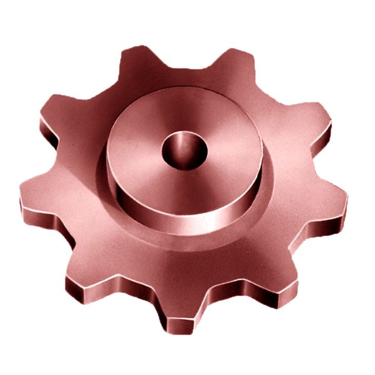
HangZhou CZPT Foundry Co.,Ltd positioned in ZheJiang Province, China. We specialised insilica sol investment decision castingwith a lot more than 20 several years and handles a hundred,000 square meters with 500 personnel. Our generation management and quality manage method completely meet the ask for ofISO 9001:2015, accredited by TUV Rheinland.
Hongsheng Makes a extensive variety of substantial-quality precision casting and machined components in stainless steel, carbon steel, alloy metal..the major fields which includes higher-velocity rail, automobile sector, maritime products, healthcare instrument, equipment components, development hardware, pump and valve parts…and so on
Benefits of Stainless Metal Castings
Stainless steel expenditure castings are utilized across a extensive selection of industry sectors for the pursuing factors:
Outstanding Corrosion Resistance: Chromium is utilized as an alloying factor in stainless metal which aids enhance its anti-corrosive qualities. Not like carbon and alloy metal, stainless metal castings demand tiny or no added surface ending. This 1 cause why stainless steel investment cast areas are utilized in industrial parts this kind of as valves, pumps, and other parts where corrosion resistance is essential.
Outstanding Visible Quality: Quality A visible appearance is feasible for expenditure forged areas that need high visible quality.
Surface Finishes: 120 RMS or better is effortlessly accomplish.
Close to Net Condition Areas: Keep away from long operate time machine components using near web investment decision solid elements.
Shut Tolerances: ±.005 inch for every inch tolerance levels can be attained
Secondary Operations and Treatment method of Investment decision Castings We Offer
Part weight: 2g to 30kgs Max dimension : 600mm for diameter or length Min wall thickness : 1.5mm Casting roughness: Ra3.2-6.4 Machining roughness: Ra1.6 Tolerance of casting: CT6 Inner core: ceramic core, urea core, water soluble wax core.
Part weight: 2g to 30kgs Max dimension : 600mm for diameter or length Min wall thickness : 1.5mm Casting roughness: Ra3.2-6.4 Machining roughness: Ra1.6 Tolerance of casting: CT6 Inner core: ceramic core, urea core, water soluble wax core.
Bevel Gears are used in a number of industries. They are used in wheeled excavators, dredges, conveyor belts, mill actuators, and rail transmissions. A bevel gear’s spiral or angled bevel can make it suitable for confined spaces. It is also used in robotics and vertical supports of rolling mills. You can use bevel gears in food processing processes. For more information on bevel gears, read on.
Spiral bevel gear
Spiral bevel gears are used to transmit power between two shafts in a 90-degree orientation. They have curved or oblique teeth and can be fabricated from various metals. Bestagear is one manufacturer specializing in medium to large spiral bevel gears. They are used in the mining, metallurgical, marine, and oil fields. Spiral bevel gears are usually made from steel, aluminum, or phenolic materials. Spiral bevel gears have many advantages. Their mesh teeth create a less abrupt force transfer. They are incredibly durable and are designed to last a long time. They are also less expensive than other right-angle gears. They also tend to last longer, because they are manufactured in pairs. The spiral bevel gear also reduces noise and vibration from its counterparts. Therefore, if you are in need of a new gear set, spiral bevel gears are the right choice. The contact between spiral bevel gear teeth occurs along the surface of the gear tooth. The contact follows the Hertz theory of elastic contact. This principle holds for small significant dimensions of the contact area and small relative radii of curvature of the surfaces. In this case, strains and friction are negligible. A spiral bevel gear is a common example of an inverted helical gear. This gear is commonly used in mining equipment. Spiral bevel gears also have a backlash-absorbing feature. This feature helps secure the thickness of the oil film on the gear surface. The shaft axis, mounting distance, and angle errors all affect the tooth contact on a spiral bevel gear. Adjusting backlash helps to correct these problems. The tolerances shown above are common for bevel gears. In some cases, manufacturers make slight design changes late in the production process, which minimizes the risk to OEMs.
Straight bevel gear
Straight bevel gears are among the easiest types of gears to manufacture. The earliest method used to manufacture straight bevel gears was to use a planer equipped with an indexing head. However, improvements have been made in manufacturing methods after the introduction of the Revacycle system and the Coniflex. The latest technology allows for even more precise manufacturing. Both of these manufacturing methods are used by CZPT. Here are some examples of straight bevel gear manufacturing. A straight bevel gear is manufactured using two kinds of bevel surfaces, namely, the Gleason method and the Klingelnberg method. Among the two, the Gleason method is the most common. Unlike other types of gear, the CZPT method is not a universal standard. The Gleason system has higher quality gears, since its adoption of tooth crowning is the most effective way to make gears that tolerate even small assembly errors. It also eliminates the stress concentration in the bevelled edges of the teeth. The gear’s composition depends on the application. When durability is required, a gear is made of cast iron. The pinion is usually three times harder than the gear, which helps balance wear. Other materials, such as carbon steel, are cheaper, but are less resistant to corrosion. Inertia is another critical factor to consider, since heavier gears are more difficult to reverse and stop. Precision requirements may include the gear pitch and diameter, as well as the pressure angle. Involute geometry of a straight bevel gear is often computed by varying the surface’s normal to the surface. Involute geometry is computed by incorporating the surface coordinates and the theoretical tooth thickness. Using the CMM, the spherical involute surface can be used to determine tooth contact patterns. This method is useful when a roll tester tooling is unavailable, because it can predict the teeth’ contact pattern.
Hypoid bevel gear
Hypoid bevel gears are an efficient and versatile speed reduction solution. Their compact size, high efficiency, low noise and heat generation, and long life make them a popular choice in the power transmission and motion control industries. The following are some of the benefits of hypoid gearing and why you should use it. Listed below are some of the key misperceptions and false assumptions of this gear type. These assumptions may seem counterintuitive at first, but will help you understand what this gear is all about. The basic concept of hypoid gears is that they use two non-intersecting shafts. The smaller gear shaft is offset from the larger gear shaft, allowing them to mesh without interference and support each other securely. The resulting torque transfer is improved when compared to conventional gear sets. A hypoid bevel gear is used to drive the rear axle of an automobile. It increases the flexibility of machine design and allows the axes to be freely adjusted. In the first case, the mesh of the two bodies is obtained by fitting the hyperboloidal cutter to the desired gear. Its geometric properties, orientation, and position determine the desired gear. The latter is used if the desired gear is noise-free or is required to reduce vibrations. A hyperboloidal cutter, on the other hand, meshes with two toothed bodies. It is the most efficient option for modeling hypoid gears with noise concerns. The main difference between hypoid and spiral bevel gears is that the hypoid bevel gear has a larger diameter than its counterparts. They are usually found in 1:1 and 2:1 applications, but some manufacturers also provide higher ratios. A hypoid gearbox can achieve speeds of three thousand rpm. This makes it the preferred choice in a variety of applications. So, if you’re looking for a gearbox with a high efficiency, this is the gear for you.
Addendum and dedendum angles
The addendum and dedendum angles of a bevel gear are used to describe the shape and depth of the teeth of the gear. Each tooth of the gear has a slightly tapered surface that changes in depth. These angles are defined by their addendum and dedendum distances. Addendum angle is the distance between the top land and the bottom surface of the teeth, while dedendum angle is the distance between the pitch surface and the bottom surface of the teeth. The pitch angle is the angle formed by the apex point of the gear’s pitch cone with the pitch line of the gear shaft. The dedendum angle, on the other hand, is the depth of the tooth space below the pitch line. Both angles are used to measure the shape of a bevel gear. The addendum and dedendum angles are important for gear design. The dedendum and addendum angles of a bevel gear are determined by the base contact ratio (Mc) of the two gears. The involute curve is not allowed to extend within the base diameter of the bevel gear. The base diameter is also a critical measurement for the design of a gear. It is possible to reduce the involute curve to match the involute curve, but it must be tangential to the involute curve. The most common application of a bevel gear is the automotive differential. They are used in many types of vehicles, including cars, trucks, and even construction equipment. They are also used in the marine industry and aviation. Aside from these two common uses, there are many other uses for bevel gears. And they are still growing in popularity. But they’re a valuable part of automotive and industrial gearing systems.
Applications of bevel gears
Bevel gears are used in a variety of applications. They are made of various materials depending on their weight, load, and application. For high-load applications, ferrous metals such as grey cast iron are used. These materials have excellent wear resistance and are inexpensive. For lower-weight applications, steel or non-metals such as plastics are used. Some bevel gear materials are considered noiseless. Here are some of their most common uses. Straight bevel gears are the easiest to manufacture. The earliest method of manufacturing them was with a planer with an indexing head. Modern manufacturing methods introduced the Revacycle and Coniflex systems. For industrial gear manufacturing, the CZPT uses the Revacycle system. However, there are many types of bevel gears. This guide will help you choose the right material for your next project. These materials can withstand high rotational speeds and are very strong. Bevel gears are most common in automotive and industrial machinery. They connect the driveshaft to the wheels. Some even have a 45-degree bevel. These gears can be placed on a bevel surface and be tested for their transmission capabilities. They are also used in testing applications to ensure proper motion transmission. They can reduce the speed of straight shafts. Bevel gears can be used in many industries, from marine to aviation. The simplest type of bevel gear is the miter gear, which has a 1:1 ratio. It is used to change the axis of rotation. The shafts of angular miter bevel gears can intersect at any angle, from 45 degrees to 120 degrees. The teeth on the bevel gear can be straight, spiral, or Zerol. And as with the rack and pinion gears, there are different types of bevel gears.
Services & Quality controlWe provide comprehensive drawings and provide every time required. EPG has established up a total established of high quality management program which is presented with advanced inspection and check gear. Complete use has been made of all varieties of innovative techniques and technological innovation to reach excelsior production.
provide interior ring EPT and toothed EPT skilled cnc router EPTT rack pinion EPT
Due to our vast product range and wealthy experiences in this market, we are self-assured to give our clients versatile and diversified companies.
Overview
Swift Details
Relevant Industries:
Constructing Substance Stores, Production Plant, Machinery Repair Outlets, Foods & Beverage Factory, Farms, Energy & Mining
Other Nation:
TianJin,China
Solution title:
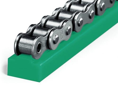
Straight Equipment Rack
Coloration:
Mother nature Color
Application:
Sector Equipment
Precision grade:
Din6
Floor treatment:
Grinding
Hardness:
45-fifty Diploma HRC
Normal:
regular
Stress:
twenty Degree
Sides floor:
Integrated
Offer Capability
Source Capacity:
10000BUILDING ON Management IN INNOVATION Our investments in investigation and growth significantly exceed the business typical. This is a result of our distinctive tradition of innovation. Piece/Pieces per Month
Packaging & Shipping and delivery
Packaging Particulars
picket/ carton
Port
TIANJIN PORT
Lead Time
:
Amount(Bags)
1 – two
three – a hundred
>100
Est. Time(times)
three
10
To be negotiated
On-line Customization
EPG supply widest range of gearbox and velocity reducers, conveyor chains and transmission parts like gear, sprocket, racks, pulley, shaves and taper bushes and so forth for different purposes
Solution present
Specification
Item title
Gear rack
Content
C45
Variety
Helical/Straight
Remedy of teeth
Ground
Hardness
45-fifty diploma HRC
Sides ground
Contain
Force
Din6-Din10
Processing
Grinding
Model name
EPG – The biggest transmission parts manufacuturer in China
Location of area
TianJin,China
Apply to gear
Slip Clutch PTO Shaft for Compact Tractor Tillers NEW SLIPCLUTCH PTO SHAFT FOR COMPACT TRACTOR TILLERS ROTO TILLERS BUSHHOG RHINO KINGKUTTER,CARONI,MASCHIO,JOHN DEERE, MOST Versions 3 distinct types of PTO in procedure: a non shear, shear pin and slip clutch — the final becoming the most costly. Implement end of non shear (r) and shear type (l) Non shear: this is a reliable yoke to yoke set up and used with the expectation that particular products will not experience any sudden stops. I determine that the ending mower does not require a shear established up as the blades will slip to a diploma getting belt driven and my other mower, the flail mower, is really forgiving in its design.
solution title
Helical gear rack
brand name
EPG – The greatest transmission parts manufacuturer in China
area of area
TianJin,China
coloration
natural
processing
grinding
Din precision
DIN6
Merchandise element
Equipment rack catalogue
How to set up gear rack
Packing & Supply
Application
Main product
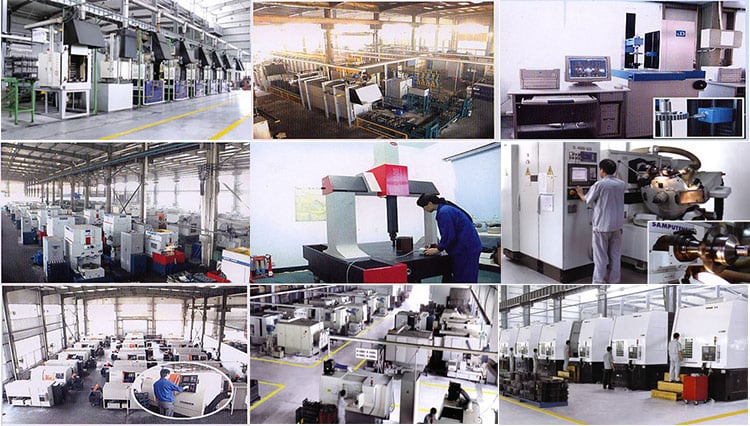
Business introduce&photograph
HangZhou EPG – The greatest transmission components manufacuturer in China Electrical Tools Co.,Ltd was launched in HangZhou in 2008 and is a skilled manufacturer and exporter that is involved with the design, growth and manufacturing.With detailed requirments, we can also build your specific made item. Our solution variety consists of all types of helical gear, spur gear, bevel equipment, equipment rack, worm equipment, sprockets,chains, bearings.Keeping in thoughts that very good support is the important to cooperating with customers, we try to meet substantial top quality specifications, supply aggressive costs and make sure prompt shipping.